|
Q2 The advantages of an active system are?
This has been written about at length by people who know more about audio than I could ever hope to learn so probably best to read what they have written.
I built my first active system in the late 70's and several since and I would never go back to multi driver passive systems.
My room includes a full 9.2 surround system and all the speakers apart from the Front Effects Height speakers are active!
One advantage that's not often discussed though is the extra freedom it gives you in regard to cross over points as well as being able to do very complex equalisation and phase corrections.
This doesn't mean that you can ignore driver response issues or crossover interactions but it is far easier to allow for these in the line level active domain than it is with a passive crossover.
Q3 Could you have made them any bigger?
Well I could have but size isn't everything you know.
To be honest they are rather large, about the same footprint and only a bit shorter than a 50's Retro style Smeg fridge.
At 1300mm high, 550mm wide and 680mm deep they are just big enough to accommodate all the drivers and considerable amount of electronics.

The system easily dwarfs Barry the bear and his friend Stanley who have been placed in the picture for the purpose of illustrating scale assuming you're ignoring everything else in the background that may give you some kind of a hint.
Barry has been known to climb the speakers and then absail down to the floor.
"Its a bloody long way to the top but well worth the climb and the view is magnificent" says the adventurous Barry.
The "balls" serve no useful purpose at all that I can see.
Probably just some Darlec (can't say Dalek else the BBC gets cranky) DNA that got in there somehow.
That's why I call them Eleven (house brand, 1 more than 10, Spinal Tap, etc) D4 (Digital 4 way) Darlecs.
Q4 Okay then, what about the width?
The width of the enclosure and to a lesser extent the height was determined by the amount of electronics I had to fit on the back and in the top.
At 550mm wide they might appear a bit slab like and defying the trend these days which is for skinny enclosures which are said to image better.
There is a lot to be said however for using a wider baffle especially if it's well damped to breakup standing waves.
Both the midrange and tweeter are mounted forward of the main baffle and on hemi-spherical sub enclosures. The wave front follows the radius of these curves which then blend nicely onto a flat baffle.
The edges of the baffle also have a radius and additional felt blocking to break up the edges, acoustically speaking that is. The entire front baffle surface is designed to generate minimal output or disturbance to what the drivers are generating.
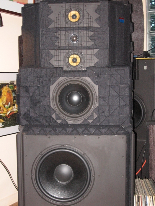
Yes they are wide and the drivers with the exception of the lower bass driver aren't even mounted off centre. Naughty me.
The red and blue rectangle is a meter which shows power levels being delivered to the drivers as well as the state of the speaker protection system. Some people find this display annoying.
Above it but not really visible because the system is turned off is the now mandatory soft blue pilot light but I'll probably get around to changing these to the much sexier soft pink ones that I use on other gear I've built recently.
The light dotted lines at the cone edges, particularly on the upper bass driver aren't really there, but are a result of resizing the pictures from 1600x1200 down to 480x360 as well as applying lots of compression.
Q5 What's with all the black felt?
The sculptured black felt blocks aren't just there to look pretty.
They consist of non uniform blocks and triangles of acoustic black felt of up to 50mm thick over a base of 12mm thick compressed wool/cotton wadding.
Not only on the front of the cabinets where the high frequency drivers are mounted but all the way down to the bass drivers and even on the sides.
Placement was trial and error with measurements taken with each addition/removal until the best positioning was found.
It's surprising how much difference an inch or two of felt can make in some positions.
All this surface treatment is designed to reduce cabinet induced effects so that we're hearing the drivers and not what they're mounted on.
The blocks improve imaging and work very well in fact which is just as well as it took me a bloody long time to cut all that felt and stick it on.
Likewise the extensive room treatment such as all the bass traps and a large angled absorbing/diffusing screen midway between the two cabinets all help to control room effects and improve imaging.
A speaker system is after all only as good as the room it's sitting in.
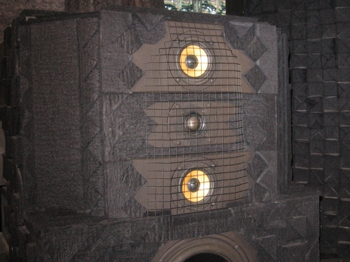
The felt is 4.8mm thick black saddle felt, made I think from rabbit fur.
Its stuck on with small dabs of silicone and the built up in layers of square and triangular pieces to create a non uniform pattern.
The camera flash has done a good job of hiding the depth of the felt blocks but they are a bit chunkier than what this photo indicates.
Q6 Does the width of the cabinet cause any response problems?
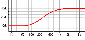
Such as Baffle Diffraction Step (BDS) which is a theoretical 6db rise, but probably less in the accoustic output of a driver with increasing frequency when mounted on a baffle that extends over about 4 octaves.
The frequency at which it starts (fMin), the +3db point (f3) and the end frequency (fMax) are directly related to the smallest dimension of the cabinet which is usually the width of the baffle.
For a typical small bookshelf type cabinet 175mm wide the frequencies are 246hz, 656hz and 3984hz.
BDS is a very real problem in single driver and 2 way systems and probably requires equalization to avoid a system that sounds very bright.
It's less of a problem in 3 ways and not really a problem at all in a 4 way system as you'll usually have 3 drivers covering the range between fMin and fMax.
With steep 4th order crossovers and therefore limited bandwidths for each driver you can simply adjust the drive levels to each driver to achieve a flat frequency response without the need to apply an inverse equalization curve to the system.
For my 550mm wide baffle fMin, f3 and fMax come in at 80hz, 210hz and 1250hz.
As f3 is the transition point where the drivers radiation changes for 4Pi to 2Pi and the crossover to the lower bass driver is 300hz and it's mounted (centre) 450mm from the floor it radiates in 4Pi for all it's range and so gains 3db in output.
The Upper Bass and Midrange are in 2Pi and the crossover point between them is 1.2khz it's very easy to achieve a flat response.
 |
|
The Baffle Diffraction Step response of a typical 500 - 600mm wide baffle.
Narrowing the baffle simply shifts the curve to the right. |
Q7 What drivers are in the system?
The golden rule of building multi driver speaker systems would appear to be to always use drivers of similiar cone construction and preferably from the same manufacturer. Being a stickler for obeying such rules I have used the following drivers.
| Driver |
Range |
Maker |
Type |
Size |
Cone |
Enclosure |
| Lower Bass |
24hz - 240hz |
Peerless |
830669 |
12" |
Coated Paper |
Sealed terminated damped line |
| Upper Bass |
240hz - 900hz |
Morel |
MW267 Neolin |
7" |
Damped Polymer Composite |
Sealed |
| Midrange |
900hz - 4.0khz |
Vifa |
MG10MD09-08 |
3" |
Glass Fibre (but soft!) |
Sealed |
| Top End |
4.0khz - 30khz |
ScanSpeak |
D2905/970000 |
1" |
Textile (Silk) |
Sealed |
|
The crossover points may seem a bit strange, especially the 900hz one but after much measuring and listening this is what works best.
Each driver was chosen on it's merits and it's abilty to do the job required but a number of other drivers were tried before determining that the current combination worked best.
Driver technology is constantly evolving though with better and better drivers becoming available so at some stage I can perhaps see at least the midrange and top end drivers being replaced.
|
|
| ScanSpeak 2905/970000 |
| Sd | 8.5cm² |
| Fs | 500hz |
| Mms | 0.45g |
| Bl | 3.5 |
| Xmax | 0.4mm |
| Qms | 3.74 |
| Qes | 0.82 |
| Qts | 0.68 |
|
|
I like this driver, a lot of people don't, probably an implementation issue but enough said about this elsewhere on the site.
|
|
|
| Vifa MG10MD |
| Sd | 38cm² |
| Fs | 81hz |
| Mms | 3.2g |
| Bl | 3.8 |
| Xmax | 1.3mm |
| Vas | 2.5L |
| Qms | 3.40 |
| Qes | 0.60 |
| Qts | 0.51 |
|
|
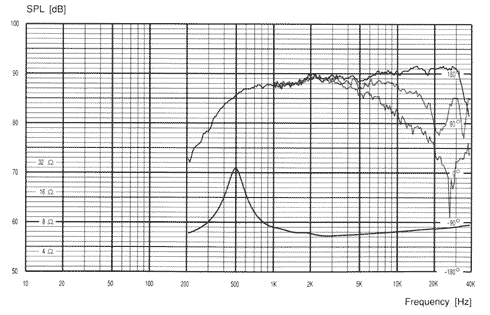
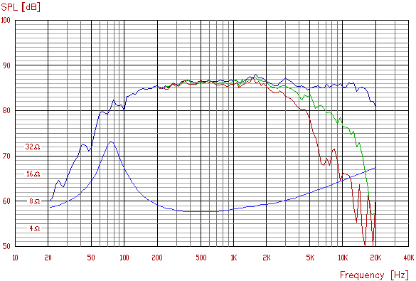
Its a pity this is only a 3" driver and not a 5" or 8" because with a response like this surely it would be suitable for the single driver fanatics.
Granted its off-axis response starts to fall away over 2k but don't all so called "full range" drivers! Only kidding guys:-)
A very much underrated driver but its 86db sensitity and low Xmax does work against its use in passive crossover systems.
|
|
|
| Morel MW267 |
| Sd | 219cm² |
| Fs | 25hz |
| Mms | 24g |
| Bl | 8.0 |
| Xmax | 8.5mm |
| Vas | 113L |
| Qms | 2.08 |
| Qes | 0.40 |
| Qts | 0.33 |
|
|
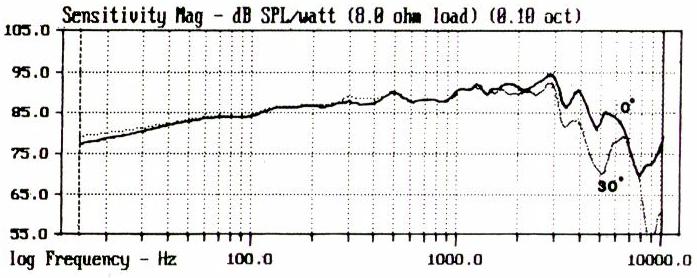
Apologies for the poor quality but this is the only response graph I've been able to find!
|
|
|
| Peerless 830669 |
| Sd | 540cm² |
| Fs | 28.0hz |
| Mms | 75.4g |
| Bl | 12.2 |
| Xmax | 16mm |
| Vas | 172.4L |
| Qms | 6.70 |
| Qes | 0.51 |
| Qts | 0.47 |
|
|
You could push this driver to 500hz with any crossover slope and probably even higher with steeper slopes without a problem.
I would rather not drive it to the 900hz required for the Vifa midrange to take over and besides the Morel MW267 does a much better job of the lower mids.
|
Q8 Aren't three drivers enough, why a four way system?
The accepted audio range is 20hz-20khz unless you're one of those single driver fanatics (sorry "single driver fans") that think that 100hz-10khz is all you need to reproduce recorded music.
Back in the real World and with the advent of SACD and other hi-rez formats you probably need a speaker system that has a flat frequency response from 16hz to at least 32khz and maybe even higher.
You could probably cover that range with 3 drivers but it's far better to use four.
The lower freqency limit in terms of a required Sound Pressure Level (SPL) for any driver mounted in a sealed enclosure is determined by is linear displacement volume. This is the surface area of the cone multiplied by the drivers Xmax which is how far the driver can move in a linear motion.
Generating realistic SPL's at any frequency is simply a matter of moving the required amount of air.
At low frequencies the amount of air you need to shift may come as bit of a surprise and could well be way beyond what the driver is capable of.
The upper frequency limit is determined by the off axis response of the driver.
This is related directly to the size of the driver, the bigger the driver the earlier the high frequency response will fall off.
For drivers that need to cross over to another driver then the response needs to extend smoothly at least an octave beyond the cross over frequency.
As good off axis response is essential and achieving a decent and consistant minimum SPL level, in this case 107db @ 1 metre for all drivers then a bit of number crunching on a spreadsheet quickly reveals that 4 drivers are needed to cover the 16hz to 32khz range desired.
The type of enclosure I'm using for the Lower Bass is a damped tapered tube as pioneered I think by Bowers & Wilkins.
Sort of like a Transmission Line enclosure except with more taper, higher fill density and the terminating end is closed rather than an open port.
So not like one at all really.
Q9 Isn't a four way active system a bit hard to setup?
I would love to say that it isn't any harder than a passive system but the truth is there's perhaps a bit more work involved.
You really do have to measure an active system and that includes all the filter sections as well as the finished system of filters, amplifiers and drivers.
Otherwise you're likely to miss things like filter values not being correct, polarity issues, incorrect drive levels etc.
It's far easier and much more accurate to measure everything, adjust as you go, listen, make corrections and so on.
I've got a boom mounted calibrated microphone mounted on a height adjustable mic stand (although usually measure at 1100mm off the floor), a DIY pre-amp and all hooked up to a laptop computer.
I use a program called REW (Room EQ Wizard) available to download for free via Home Theater Shack.
 |
|
Mike on stand, power supply, gain control, mike pre-amp and the laptop running REW.
|
 |
|
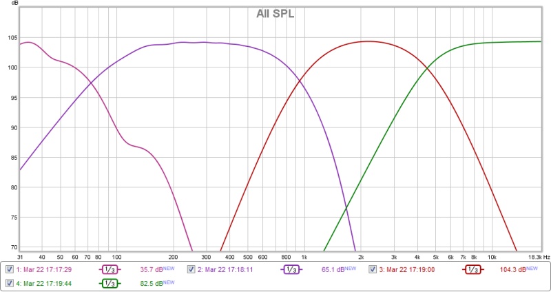
The on axis acoustic response of each driver measured at 250mm from the driver.
|
Q10 Are the drivers time aligned?
Yes they are with the drivers mounted on an arc because as we all know a line of points of equal distance from a fixed point is a curve.
This isn't that hard to do after an average listening position and height is determined.
Bearing in mind though that a multi driver speaker system can only ever be perfectly time aligned for one point in the room but at least achieving this for an average listening position is a big step up on speaker systems that are not aligned for any point in the room!
A multi driver system where the drivers are not perfectly in phase with each other, at least at the cross over points will never image properly and your chances of achieving a decent soundstage are minimal.
Q11 Are the drivers decoupled from the baffles?
No, all drivers apart from the tweeter are firmly mounted to the baffles which are nice and thick and firmly joined to a equally rigid and properly built non resonant cabinet.
A rear magnet brace is also employed for all drivers, again with the exception of the tweeters.
I see very little point in having a driver loosely rubber mounted to a baffle so that the entire driver can move.
Surely this is what the cone is supposed to do, on its own and against a magnet which should be staying in the same place!
Q12 Are the enclosures decoupled from the floor?
If your floor is very loose and vibrates then it's probably a good idea to isolate the speaker enclosure from it, but driven hard enough the floor is going to vibrate anyway simply because of all the bass energy in the room.
If your floor is very solid however I guess it's a good idea to clamp the speaker enclosure to it to damp any vibrations in the enclosure as it's mass is a lot less than the floor.
My floor is very solid/rigid/dead/inert, being solid floorboards on 90mm x 45mm hardwood battens securely DynaBolted to a 200mm thick concrete slab.
The speaker enclosures are also very solid and weigh a lot more than I do, 143kg in fact (them not me) so I reckon they're not going anywhere and are unlikely to be moved about by a few light speaker cones vibrating back and forward a few millimetres.
Therefore I figure that they can take care of themselves and as such sit on 100mm x 100mm squares of a rubber vibration isolation material commonly referred to, in the mechanical services industry as "waffle pad".
I think that makes them decoupled but I frankly I don't think it matters.
Q13 What are they made of?
Mostly a mixture of medium density fibreboard (MDF) and variable density particle board (VDPB?).
Each have their advantages and when used as a composite material have good resonance properties. 18mm and 25mm thick sheet is used and the minimum panel thickness is 36mm, with 50mm baffles and back panels. 40mm x 40mm hardwood, mainly Jarrah is used for bracing where needed. Sand filling is used in some sections of the upper bass and midrange enclosures.
I'm lazy so I use course thread posi drive screws and a screw gun, but all holes are pre drilled with a counter sinking drill.
I also glue everything using lots of good quality wood glue.
Q14 Are the enclosures lead lined?
Yes the upper bass and midrange sealed enclosures are all fully lined with 15kg/m² lead sheet.
The lower bass enclosure is lead lined everywhere it matters like the bends, in fact most of the internal panels are lined.
The lead is glued over its entire surface using generous amounts of glue.
The lead lining includes moulding the lead to the routed back of the baffles where the driver mounts right up to the driver frame so that the entire internal surface of the enclosure is lead lined.
I realize that unlined wooden boxes that resonate often impart a certain musical quality to what they're trying to reproduce but it's not something I'm trying to achieve.
Q15 Are they filled and with what?
All the enclosures are lined with 12mm thick compressed wool/cotton wadding fully glued to the lead and then the remaining void is filled with teased out long fibre raw wool.
Fill density averages 16gm/litre in the lower bass enclosure and is 48gm/litre in the upper bass and midrange enclosures.
Raw wool is messy stuff and a lot of work is involved in getting to a state where you can fill a box with it but it does work very well.
Far better than polyester or other man made substances even those that are said to mimic the behaviour of long fibre raw wool.
Q16 Are those sub woofers behind the speakers and at the back of the room?
Yes indeed they are and mentioned here because they're an integral part of the main speakers.
There are two "subs" behind each speaker, both use the same driver as the main speakers except one is mounted in a standard sealed enclosure and the other in a reasonably big ported box.
Each has it's own amplifier, again the same as the main speakers and the whole lot (all four amplifiers and drivers) is driven by a miniDSP board.
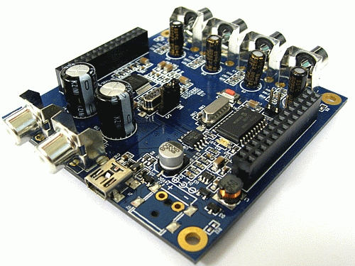
Doing all this in the digital domain makes it far easier to achieve a flat in room response and blend the subs to the mains.
It's also very nice to be able to control all four channels from a single point and adjust crossover frequencies, slopes, levels and EQ on the fly using a laptop rather than getting the soldering iron out.
There are also 2 additional TL enclosures with 10" drivers at the rear of the room as the more points that you introduce low bass into a room the more chance you have of getting an even response.
And just in case you think that 6 12" drivers and 2 10" drivers mounted in 8 enclosures, each driven by a 150w @ 6ohm amplifier is a bit much, then refer back to paragraph 4 of the response to Question 8.
For further reading on the use of multiple lower bass drivers you could read the AES paper #5062 titled "Subwoofers: Optimum Number and Location" by Todd Welti.
How they are being driven is also important and borrowing a paragraph from the Multi channel pre-amp article...
"Bass management consists of the abilty to derive stereo sub outs for the front left and right subs derived from the main left and right (stereo) signal and a separate mono sub signal is sent to the two rear subs.
All this happens when the LFE switch is in the 9 o'clock (2.1) position with the 2.1 gain control (to the left) controlling the "mix" level for the rear subs.
In short, I'm running stereo subs for two channel audio but this has only been a recent upgrade but something I should have done long ago because it's a vast improvement over mono subs."
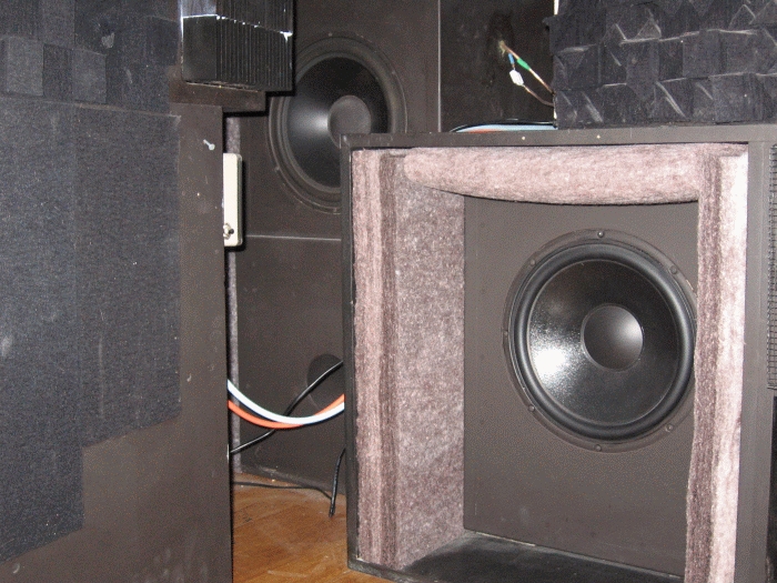
|
|
I'm still a fan of transmission lines and people are generally impressed with the size of the things and tend to ask questions.
You can achieve much the same result though with a much smaller low Q sealed box.
|
Q17 What sort of filters do you use?
The same 4th order Linkwitz-Riley filters that everyone else uses and for the same reasons I guess.
They sum flat, are low Q and the cutoff slopes are steep enough to reduce the cross over region where you're getting output from both drivers.
Following the success of using a miniDSP board to drive my sub woofers and taking into account that most speaker/room interactions take place below 300-400hz it seemed a good idea to drive both the lower and upper bass drivers via DSP rather than analog.
The problem with my system or to be more specific the speaker/room interaction of my system was that after extensive speaker placement and listening/measuring sessions it became only too obvious that every pair of possible speaker placement points were a compromise.
If I positioned the speakers for the best soundstage for width, centre fill and image depth the frequency response below 400hz was all over the place.
Worse still was that because of my non symmetrical room layout the responses of both speakers didn't match each other and that can't be good.
Positioning the speakers for the smoothest frequency response caused the soundstage to suffer and was a compromise in itself because no two mirror image positions worked for both speakers.
The implementation of DSP has allowed me to position the speakers for the best soundstage and then fix the response issues that this placement causes.
At first I tried a hybrid crossover where I retained the analog crossover for the midrange and tweeter and only used the miniDSP board for the lower and upper bass.
I've now ditched the analog crossver completely after comparing the ADC/DSP/DAC route against analog with several op-amps and lots of resistors and capacitors.
The all digital setup sounds better but to be honest it's partly due to being able to correct errors in the phase and frequency response that would require a hell of a lot of work and extra components in the signal path to do in the analog domain.
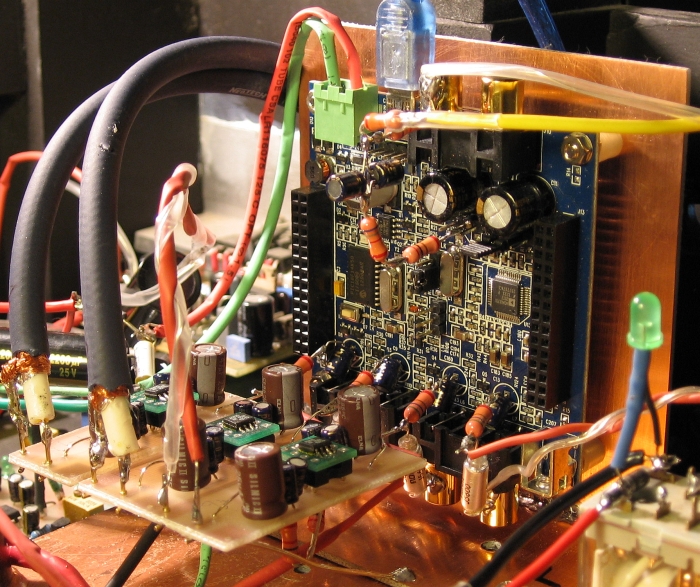
A slightly tweaked MiniDSP 2x4 board in that I'm bypassing both the input and output components and using my own.
Voltage divider on the input using Takman resistors and the required input coupling cap is a pair of 22uf BlackGate NX Hi-Q in Super E-Cap configuration.
Output coupling cap (again required as there's 1.4 volts on the output of the DACs) is another 22uf BlackGate NX Hi-Q.
Low pass filter is a 560 ohm resistor and 5600pf polystyrene capacitor.
The op-amp buffers are required because of the 900mv output limit on the 2x4 unbalanced boards and the fact that power amps being used need more voltage than that.
Bass and Upper Bass have +9db gain and the Mid +6db.
Chips are AD825's.

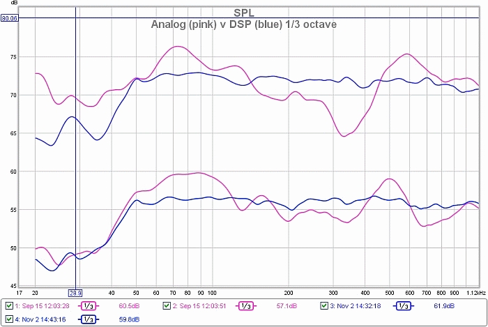
20hz to 1khz SPL plot of Analog crossover (Pink) and DSP crossover (Blue), 1/12 octave smoothing, measured at ear height and at my preferred seating position.
Main speakers only, all subs are off. The spikes at 50hz are measuring system related.
As can be seen the use of DSP in pretty effective in taming the wild swing in the peaks and dips for the in room response.
Note: For people that use a well known "Room EQ" system and are used to seeing a computer generated simulated 1/1 octave smoothed room response that is a flat line, well that doesn't really happen in real life.
 |
|
1/3rd octave smoothing better illustrates the improvement in reducing the extend of the peaks and dips in the response and the differences between the left and right channels.
|
Q18 What op-amps, power supply, etc?
Currently using AD825's on Brown Dog adapter boards for the SOIC packaged chips.
Supply rail decoupling capacitors are 0.1uf Black Gate NX Hi-Q, local reservoir capacitors are Elna Silmic II series, resistors, Takman carbon.
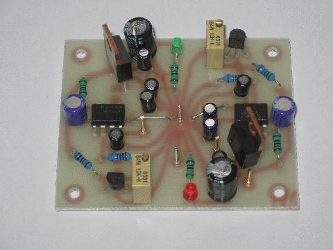
Power supply consists of +/-18V LM317 pre-regulators followed by +/-15V Sulzer-Borberly low noise regulators.
 |
|
My implementation of the Sulzer-Borberly low noise regulators. Output is +/- 15V from a +/-18V input from LM317 pre-regulators.
|
Q19 What about impedance correction and resonant frequency notch filters?
Driver impedance correction has to be done at the driver with passive components and whilst you can implement active notch filters to tame the drivers resonant frequency peak by not driving it at that frequency it's better to passively tame the impedance peak that's causing it.
Impedance correction networks are easy to design but you do need the Q data for the driver and these numbers are missing from the current data sheets.
In case you're interested or wish to design your own networks or check my figures, here are some typical figures arrived at by testing a batch of drivers and averaging the results...
You will also need...
The 500hz series notch filter is comprised of Cn, Ln and Rn and the "rising impedance" correction network consists of Ce and Re.
And the formulas are...
Cn = 0.1592/( Re X Qes X fs )
Ln = ( 0.1592 X Qes X Re ) / fs
Rn = Re + (( Qes X Re ) / Qms)
Rc = Re X 1.25
Ce = Le / (Rc X Rc )
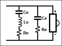
|
|
Calculated |
Nearest |
|
|
Calculated |
Nearest |
| Cn |
82.6 mfd |
82 mfd |
|
Ce |
0.29 mfd |
0.33 mfd |
| Ln |
1.23 mH |
1.2 mH |
|
Re |
5.8 ohm |
5.6 ohm |
| Rn |
5.73 ohm |
4.7 ohm |
|
|
|
|
|
|
With the values involved to create a 81hz notch filter (600 mfd and 6.48 mh) and as the resonance is nearly 3 octaves below the nominal 590hz crossover point anyway I didn't bother.
The voice coil induced rising impedance correction network is easy to implement with two off the shelf standard value components, Ce and Re.

|
|
Calculated |
Nearest |
|
|
Calculated |
Nearest |
| Cn |
595 mfd |
600 mfd |
|
Ce |
6.98 mfd |
6.8 mfd |
| Ln |
6.48 mH |
6.47 mH |
|
Re |
6.8 ohms |
6.8 ohms |
| Rn |
6.5 ohms |
3.3 ohms |
|
|
|
|
|
|
Q20 Okay moving on, what sort of power amplifiers are being used?
The amplifiers are chosen simply on the basis of the best amplifier being selected to cover each frequency band which is a real advantage of active speaker systems.
Bass drivers need lots of power but not much finese.
Tweeters need very little power but very high quality and low distortion.
Midrange amplifiers just need to sound right.
Building a single amplifier that does everything well is difficult and it's far easier to build multiple amplifiers each refined for the job it's required to do.
| Band |
Power |
Design |
Class |
Output Devices |
| Lower Bass |
125W |
Leo Simpson & Bob Flynn |
AB |
MJL21193 / MJL21194's |
| Upper Bass |
125W |
Leo Simpson & Bob Flynn |
AB |
MJL21193 / MJL21194's |
| Midrange |
55W |
Hugh Dean |
AB |
2SC5200 / 2SA1943 |
| Top end |
15W |
Leo Simpson |
A |
MJL21193 / MJL21194 |
|
You can use just about any amplifier you like to drive bass drivers as long as it has lots of grunt both in terms of power output and current ability and a very low output impedance.
Good bass also requires very good low impedance power supplies with big transformers.
The bass amps I use are nothing special but can supply 150W into the 6 ohm load that the lower and upper bass drivers present at published total distortion levels of 0.002%.
The midrange is a bit trickier because while the bass anchors the music and the top end adds the sparkle, it's the midrange that you're listening to most of the time and it really needs to be right.
After lots of listening tests and ignoring numbers written on paper I decided on Hugh Dean's superb 55W AKSA amplifiers with Nirvana mods and a few changes of my own.
The top end requires ultimate quality and a standard Class AB amplifier just can't deliver the distortion figures required because distortion in all solid state amplifiers increases with frequency.
Class A is the only way to achieve low distortion and low distortion is the only way to achieve musical accuracy. The bass amps produce 0.03% distortion @ 20khz which is reasonable but the class A amplifiers used are 15 times better with total distortion of only 0.002% @ 20khz dropping into 0.000X% territory at lower frequencies.
Parts used are nothing special.
Resistors are standard 1% 1/2 watt metal film.
Electrolytic capacitors are Rubycon ZA, Elna Silmic II or Black Gate NX Hi-Q's.
De-coupling caps are MKP film and Silvered Mica are used for the lag compensation cap.
I match all the transistors used as diff amps and current mirrors and for any output transistor pairs this includes both hfe and Vbe.
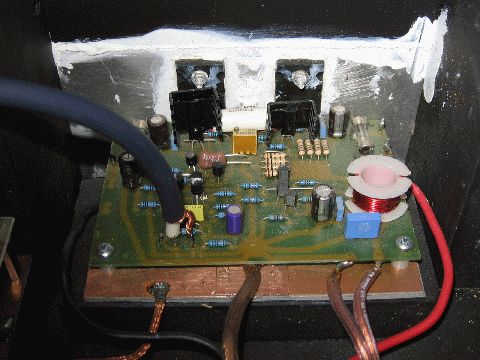 |
|
Top end amplifier, 15w class A, powered by regulated +/-21V supply.
|
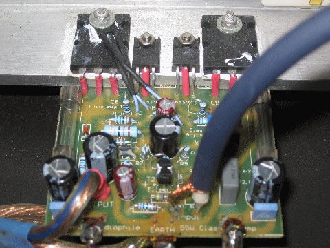 |
|
The midrange amp, Hugh Dean's superb AKSA 55W.
|
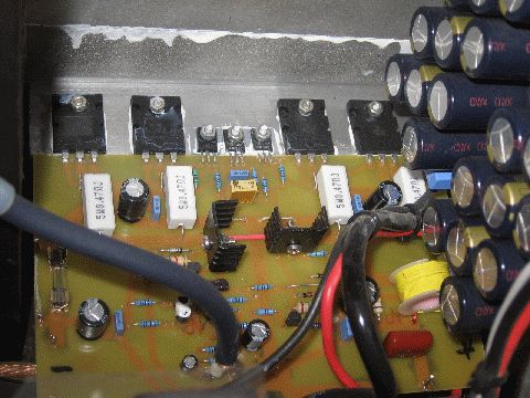 |
|
Lower and upper bass amps, 125w class AB.
|
Q21 Why all the capacitors in the power supplies?
A single big value can type electrolytic may be convenient but it's not the best way to achieve a high ripple current rating and low impedance and ESR.
Multiple lower value capacitors in parallel offer far better performance and after looking at lots of spec sheets I decided to use 1200uf/63V Panasonic FC series electrolytic capacitors for all the power supplies.
The bass amps use banks of 14 capacitors per supply rail for a total of 16,800uf which may not sound like a lot but with a combined ripple current rating of 41 amps, an impedance of only 2.2 milliohms @ 100khz and a 5000 hour rating at 105ºC you won't find a single can type electrolytic that even comes close.
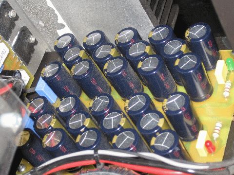 |
|
The dust on the caps improves the sound in much the same way that it improves wines laid down in a cellar.
|
Q22 Anything else of note in the power supplies?
Nothing special but they do start with a good mains filter which is a two stage setup which attacks both common mode and differential mode mains borne interference.
I use big toroid transformers rated at twice the nominal output of the amplifiers, 300W for the bass amps, 160W for the midrange and also 160W for the top end as it's class A and chews up 85W for it's 15W output.
Each power amplifier has it's own power supply, as does the filter board and the main control board and each of the speaker protection boards (solved a possible earth loop problem).
Good fast diodes are cheap so I use 10 amp & 20ns BYQ28E-200 and 20 amp & 25ns BYV32E-200 which cost less than $2 each.
I also shunt each with a small snubber film cap and series resistor but it's probably not making much of a difference.
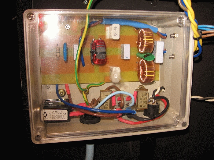
This is the mains filter and remote 240V switching. The filtering is for both common and differential noise modes.
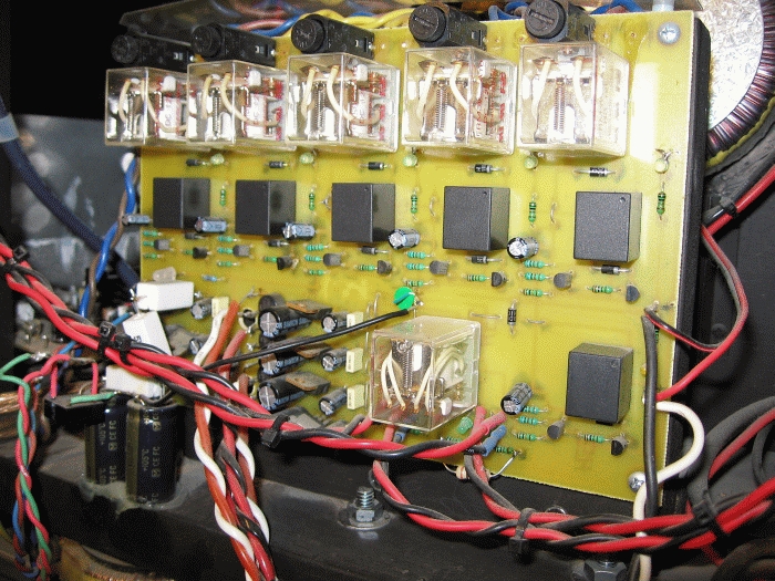
In order to safely power up and power down the system I thought it best to add a sequential switcher.
This turns on the crossover power supplies first, then each power amp supply in turn and when they've all settled down it connects the drivers.
Turn off is the reverse but even power interuptions will disconnect the drivers instantly before the amplifiers start to power down.
It sounds like an old fashioned telephone exchange when powering up but it works and has been bullit proof so far.
Q23 Where does all this live?
It's a pretty big room at 6800mm x 5000mm (22.3ft x 16.4ft) and with a average ceiling height of 3100mm (10.2ft) that works out to be a tad over 100 m³ (3700 ft³) and that's before it opens out onto a 1600mm wide passageway.
A good size for decent audio for reverberation, standing wave reduction (1.0 : 1.6 : 2.2 ratios) and such but it does require a lot of power to achieve realistic sound levels.
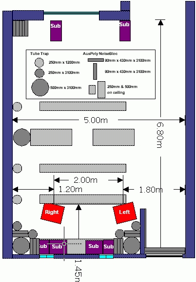
Drawing of the room showing the positions of the speakers (orange), subs (purple) and acoustic treatments (grey), mainly 500mm and 250mm cylindrical bass traps.
Some of the vertical bass traps run floor to ceiling for room mode control whilst others are purely to control reflections.
Walls are double solid brick, except the front and stub wall which are stud but filled with Rockwool and lined with 16mm FyreCheck plaster.
One side wall is covered in an offset metal stud wall using 10mm plasterboard and the cavity filled with Rockwool so as to aid bass absorption.
Floor is solid timber over concrete slab, windows are double glazed laminated glass and glass blocks.
Q24 Masking tape on the floor, really?
Positioning the speakers correctly and accurately is important.
Especially when you have to move them like I do to cater for both audio use and Home Theatre where I have to move both speakers outwards so they clear my Scope (2.35:1) screen.
Luckily, on both counts that the room doesn't have carpet.
Having them point in the right direction (toe in) is also important but forget about tape measures and such stuff.
A Laser pointer and suitable target (vertical black line on paper) at the midpoint between the speakers placed where you want both of them to point to is much easier.
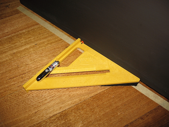
A plastic Stanley builders square, some felt on the bottom so it sits flat and a Laser pointer stuck to it with some Silicone makes a very good jig for aligning speakers.
The orange dot marks the centre line of the speaker (drivers) and this is aligned with the central axis of the Laser pointer.
Q25 The flat black finish is a bit drab isn't it
Red goes faster and black sounds better.
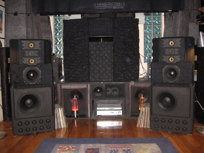 Besides black fits in perfectly with the rest of the room.
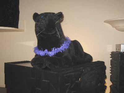
Q26 What's with the Panther?
The Panther, who's name is "Perry" by the way is an intergral part of the system as he forms part of the complex acoustic absorbtion system that helps the speakers and the room to perform properly.
 |
|
"Perry" is looking particularly festive in this photo with his decorative purple collar on.
It was actually put on him at Christmas but all attempts to remove it since then have met with fierce resistance.
He can be a vicious little bugger when he wants to be.
|
|


