| Home Turntable Phono CD Pre Speaker Multi Pre HT |
| CD |
The Oppo BDP-83 universal player is a remarkable machine because not only does it play Blu-ray, CD, DVD, DVD-Audio and SACD format disks but it plays them very well. As a digital transport it's probably without equal irrespective of cost but one area in which it does fall short is it's analog audio outputs. Not that many of us use analog connections these days for movies and multi-channel music as bitstreaming LPCM, Dolby TrueHD, DTS HD Master Audio and in the case of SACD on this player pure DSD via HDMI to a suitable processor is a far better way of doing it.
However my interest in this machine apart from movies on Blu-ray and DVD of course is two channel CD and SACD playback via the two channel analog outputs. Improving the quality of that audio and what I've done to the player to achieve this is what this article is about. The more knowledgeable of you are at this point perhaps wondering why if it's analog audio quality I'm after then why aren't I using the 83SE with it's better (on paper at least) DACs and improved analog board. The answer to which is that I think I can improve the quality of the stock 83 way beyond that of the 83SE for about the same cost as upgrading to an 83SE, not that money really comes into it.
And to further answer this I don't think it's the superior DACs alone in the 83SE that account for the better analog sound. What Oppo have done in the 83SE is to remove most of the junk in the signal path after the DACs that the 83 has such as cheap coupling capacitors, one op-amp and the transistor muting circuits all of which screw up the sound. They've also improved the power supply to the DAC and most important of all and this is where the DAC does make a difference, they've reduced clocking jitter because the ESS Sabre DACs with their Time Domain Jitter Eliminator are essentially jitter free. Apart from that the players are exactly the same and I suspect that once modded both players would be very close to each other in performance and heaps better than stock.
The Cirrus Logic CS4398 DAC that's used in the 83 is found in a number of high end dedicated SACD players and I am familiar with the "sound" of them and it's a sound I like, whereas the ESS DACs are for me at least an unknown quatity. So the plan is to improve everything around and after the DAC, and it's power supply and to eliminate jitter by fitting a decent clock. I also plan to do the usual things such as damping the drive and chassis as well as adding RF shielding, better connectors etc. I'm already running the machine via a decent mains filter and proper 1:1 isolation transformer but that's all external.
Disclaimer: This article is a personal account of the modifications I've made to my player as I seek audio nirvana. And that's all it is, it's not a "how to guide" and there's no suggestion by me that you the reader should use any of the information supplied here as a basis for modifying your own equipment. All opinions, right or wrong are my own and whilst I do my best to ensure there are no errors there may well be. Any information supplied is supplied "as is" and without any warranties expressed or implied.
| Analog stage - Plan A - Improving what's there |
The analog stage for the Oppo is pretty straightforward. The four balanced left and right outputs of the Cirrus Logic CS4398 DAC (U1) are fed through four 100uf coupling caps (CE7, CE8, CE9 and CE10) to the first 5532A dual op-amp (U5) which is running in differential mode and performing the usual filtering required as per the CS4398 spec sheets. The output of this is direct coupled to a second 5532A dual op-amp (U10) which is a unity gain buffer/line driver the outputs of which is capacitor coupled by a pair 100uf caps (CE6, CE18) each with a small 100pf (?) film bypass cap (C151 and C152) to the following mute section, some additional filtering and then onto the output RCA sockets.
The first thing I did was replace the board mounted stereo RCA sockets with decent insulated chassis mount ones mounted to the rear panel using the holes that the original ones went through. And then I bypassed the entire mute section by removing CE6, CE18, C151 and C152 and wired the output sockets directly (via a 47 ohm resistor) to the outputs of the second 5532A buffer/line driver op-amp. The resistor is there to protect the op-amp in case you short the ouputs and also to isolate it from any cable effects.
It's hard to believe but even this small change makes an audible improvement to the two channel output of the Oppo. The removal of the muting circuit doesn't appear to cause any issues as there are no clicks on disk changes or track seeks but some minor op-amp squeals at turn on/off so I'll need to remember to turn down the volume when turning the player on or off.
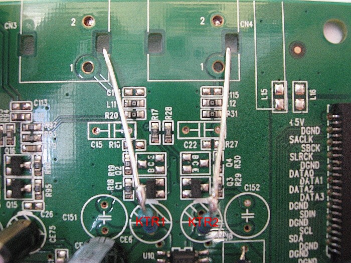 |
| The resistors connect from the vacated holes for CE6 and CE18 nearest the 2nd 5532A op-amp directly to the RCA output socket. |
| Designation | Description | Replaced with |
| CN3, CN4 | RCA Socket | Better ones |
| C151, C152 | 100pf | Remove |
| CE6, CE18 | 100uf/16V TK | Remove |
| KTR1, KTR2 | Additional component | 47 ohm |
And that's it for the quick fix of removing bits that aren't really needed so time to get serious and start replacing existing bits with better quality components.
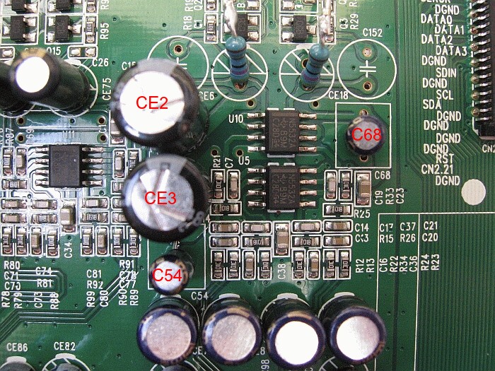
The first thing to tackle are the two 5532A op-amps or at least the +/- 12V supply rail storage/filter and decoupling caps.
 |
| Designation | Description | Replaced with |
| CE2, CE3 | 220uf/25V TK | 220uf/16V Elna Silmic II |
| C54, C68 | 684J63 | 0.1uf/50V Black Gate NX Hi-Q |
The next logical step is to replace the adequate but not very inspiring 5532A op-amps with something better.
Looking though the parts draws I discovered that my choice of dual SOIC op-amps was limited.
Eventually I settled on a LM4562MA (National Semiconductor) for U5 which is a good choice for the filter stage because these are quick, clean and accurate.
Additional supply decoupling caps KTC5 and KTC6 are soldered directly to the supply pins of this chip, the other ends tied together and then to a nearby earth point on the board.
For the output buffer/line driver U10 I decided to use something not only a bit "warmer" but with good drive ability so I managed to fit in a pair of Burr Brown OPA627BP's each on a small PCB and with some additional decoupling caps.
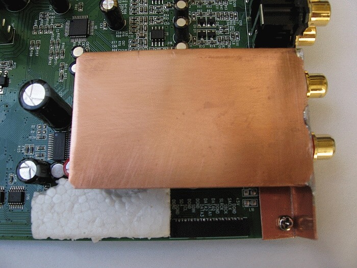 |
| It's not that my attempt to fit six biggish components into a space where a very small SOIC chip used to be doesn't work, it's just that it looks a tad messy. Good thing this piece of copper shielding covers it all then isn't it. Rather than mount the RCA sockets on the back panel which makes wiring them up not only messy but difficult I made up a small right angle bracket and the sockets mount on it. This is attached to the analog board and also by screws to the back panel. The small piece of polystyrene foam attached to the board is to insulate it from a rather hot heatsink directly under it. |
| Designation | Description | Replaced with |
| U5 | 5532A | LM4562MA |
| U10 | 5532A | OPA627BP x 2 |
| Additional components | KTC1, KTC2, KTC3, KTC4 | 0.1uf/50V Black Gate NX Hi-Q |
| Additional components | KTC5, KTC6 | 0.01uf/50V Monolithic |
| Additional components | KTR1, KTR2 | 75 Ohm Riken |
| Analog stage power supply |
As the active op-amp filter and output buffer are being kept I thought it best to improve the main +/- 12V power supplies with better storage/filter and decoupling caps. I'm using Rubycon ZL's before the regulator and Elna Silmic II's after.
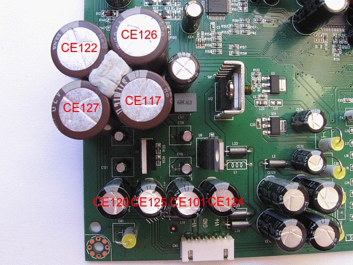 |
| Maybe I should have gone for the 16V and not the 25V Elna's as these are a tight fit. The standard regulators aren't that bad being adjustable 317 and 337 types. The stock parts remaining are for the +5V supply for the multi-channel DAC as I've not changed anything in the multi-channel section. |
| Designation | Description | Replaced with |
| CE101, CE120, CE124, CE125 | 470uf/25V TK | 470uf/35V Rubycon ZL |
| CE117, CE122, CE126, CE127 | 470uf/25V TK | 470uf/25V Elna Silmic II |
| CE116, CE119, CE121, CE123 | 684J63 | 0.1uf/50V Black Gate NX Hi-Q |
| Analog stage - Plan B - KISS (Keep it Simple Stupid) |
What's really nice about the Cirrus Logic CS4398 is that it's a voltage output DAC with balanced outputs. This avoids possible slew rate issues in the I/V stage that current output DACs require and it also makes it really easy to implement what a lot of people regard as the best analog output stage possible for this DAC which is transformer coupling. Offsetting the cost of the transformers is the fact that all you have to do to the analog stage is remove four capacitors.
You don't need to do anything to the analog power supplies or fret about what op-amps or discrete modules to use because you're using none of it. This saves a lot of parts as detailed above and more importantly time which if you're paying someone to mod your player is mostly what you're paying. Even though the current active setup is sounding pretty nice it's no doubt something to consider in the future but it would of course depend on being able to source some suitable transformers.
That day came and went because when I tried to source those suitable transformers from a local designer of some note I was told that he couldn't possibly sell them to me unless I had a full mod package installed on my machine because there wasn't enough profit margin on just the transformers. Sort of like walking into a green grocer to buy an apple and being told that you can't have the apple unless you also buy a banana and a pineapple. I explained that I'd already modded the player and only wanted the transformers and was happy to pay what he considered a fair price for them, including a fair profit, but no go. This left me slightly perplexed to say the least and the project got put on hold for some time.
Time passed and then one day with renewed vigor I set out once again to source some suitable transformers. Apart from being made in Sweden I'd been hearing very good things about Lundahl line transformers when used with the CS4398. So when a mate mentioned that a mutual friend had obtained Lundahl's from a local supplier I thought why not.
Why not indeed but sadly when I contacted this local supplier I found their delivery time frame, not to mention their draconian terms and conditions to be totally unsuitable. What is it with Australian retailers and their inability to sell you what you want and yet they complain that things are hard and sales are down. So then I tracked down the Australia importer and distributor for Lundahl and they were happy to supply them but quoted a three week delivery time Ex Sweden as they didn't have stock. They also quoted a price that was 33% more than the first offer I'd had. I did reply to their quote and point this out. I was polite, I was just trying to negotiate a more reasonable price but I never heard back from them.
Time to turn to the InterWeb where I found the USA distributor for Lundahl, K&K Audio. Exchanged a few emails and for the cheapest price I'd been quoted so far, by far, including freight they arrived here within seven days. Talk about friendly, prompt and efficient service. Australian distributors and retailers could certainly learn a thing or two from them. So if you're in Australia or anywhere else for that matter and you want some Lundahl transformers I can highly recommend that you get them from K&K Audio. Okay, enough whinging about the inablilty of Australians to do business and moving onto building stuff, yay.
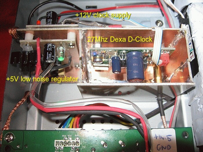
Due to the fact that I've used the space at the front of the player to the left of the transport to house a low noise power supply for the DAC, power supply for the clock and the clock itself, I had a slight problem. Because this is where most other modders put the transformers as there isn't any room anywhere else.
 |
Thinking laterally and being a firm believer in function over form, substance over style et al. I took what some would regard as a radical approach. Rather than house the transformers inside the case I'd put them outside of it. And to keep lead lengths to a bare minimum the obvious place outside the case was on top of the case directly above the DAC chip.
Yes that involves drilling a hole in the top case of the player. It is only a small hole of 10mm in diameter and there is only one. I do understand that some will find this rather distressing so if you feel the need for a calming beverage and a lie down before reading further please do so. Be reassured though that I haven't included photo's of this barbaric act of vandalism, just the finished product.
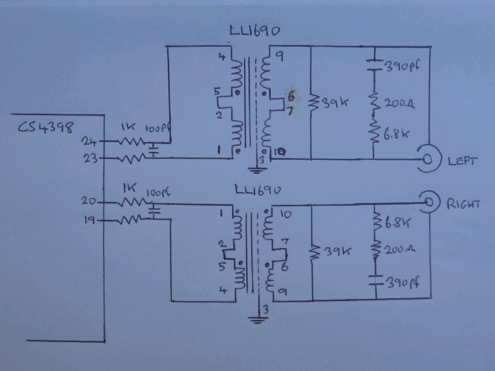
The circuit is the standard serial connected primary and secondary as suggested by Lundahl. I've also used their suggested, or close to them loading and filter values on the output consisting of a 39k resistor in parallel with a series 7k and 390pf. The primary side is simply fed via 1k resistors from both the Out + and Out - from the CS4398 chip.
 |
| Designation | Description | Replaced with |
| CE7, CE8, CE9, CE10 | 100uf/16V TK | Remove |
| KTTran1, KTTran2 | Additional component | Lundahl LL1690 1:1 transformer  Lundahl LL1690 data sheet Lundahl LL1690 data sheet |
| KTR1, KTR2, KTR3, KTR4 | Additional component | 1k Takman Carbon Film |
| KTC1, KTC2 | Additional component | 390pf Polystyrene |
| KTR5, KTR6 | Additional component | 39k Takman Carbon Film |
| KTR7, KTR8 | Additional component | 6.8k Takman Carbon Film |
| KTR9, KTR10 | Additional component | 200 ohm Takman Carbon Film |
| KTC3, KTC4 | Additional component | 390pf Silver Mica |
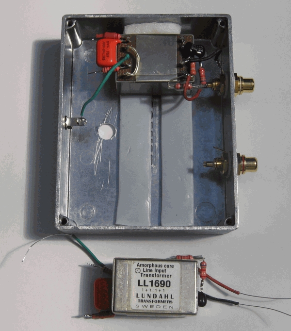 |
| The Lundahl LL1690 transformers are mounted in a small die case box which provides excellent shielding. They sit on strips of Blu-Tack to both fix and provide damping. The filtering and loading components are mounted directly on the transformers. |
 |
| The finished product with both transformers mounted and wired. Additional Blu-Tack to the sides and on the top of the transformers helps hold them firmly. White blobby things are packing foam. A small amount of silicone holds the die cast box to the top cover of the player. The very short input wiring enters via the hole at the front of the box. Both the transformers and the box are earthed via the players chassis earth. Please note that the layout differs from the previous photo in that the .0047uf capacitors have been replaced by 390pf. |
| The DAC |
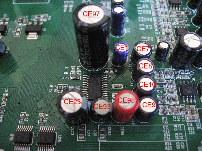
There's not much you can do around the DAC chip except upgrade the storage caps for the 3.3V and 5.0V supply rails and perhaps add some decoupling caps. There's also some voltage reference caps, CE1, CE93 and CE95 that I replaced with some better ones.
* The 100uf coupling caps on the balanced outputs of the DAC are replaced with pairs of 47uf/6.3V Black Gate NX Hi-Q in Super E-Cap configuration. Four on one side of the board and the other half of the pairs on the other side of the board as are the additional decoupling caps, KTC7 and KTC8 which are mounted directly on the pins of C23 and C97.
 |
 |
| The Blu-Tak is to damp vibrations. |
| Designation | Description | Replaced with |
| CE7, CE8, CE9, CE10 | 100uf/16V TK | 2 x 47uf/6.3V Black Gate NX Hi-Q * |
| CE97 | 470uf/25V TK | 470uf/25V Elna Silmic II |
| CE23 | 220uf/25V TK | 220uf/16V Rubycon ZA |
| Additional components | KTC7, KTC8 | 0.1uf/50V Black Gate NX Hi-Q |
| CE1 | 3.3uf/50V Acon | 3.3uf/16V Panasonic Oscon |
| CE93 | 33uf/16V Acon | 33uf/35V Rubycon ZA |
| CE95 | 100uf/16V Acon | 100uf/6.3V Black Gate NX |
| DAC power supply |
As a DAC is only as good as it's power supply it's time to beef that up with better storage/filter and decoupling caps.
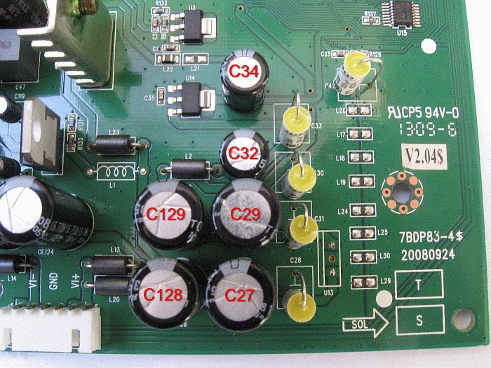 |
| Designation | Description | Replaced with |
| CE27, CE29, CE128, CE129 | 470uf/25V TK | 470uf/35V Rubycon ZL |
| CE32, CE34 | 220uf/25V TK | 220uf/25V Rubycon ZLG |
| C28, C30, C31, C32, (C42) | 684J63 | .01uf/400V Vishay 1839 |
| U13 | 7805 | +5V low noise regulator |
 |
| +5V low noise regulator, as well as the +12V regulated supply for the clock and the Dexa D-Clock which is mounted in a shielded enclosure. The red, green and blue LEDs light up this corner of the chassis rather well. Very colourful at night, pity the top cover hides it all. |
| Low jitter clock |
As is usually the case with players that spin silver disks the master clock in the Oppo is just a crystal and two capacitors variety. As such it has very high jitter and unless it's replaced then all the other mods being done will amount to not very much at all. After removing X1, C194 and C197 the new clock signal feeds into the vacated pad closest to the heatsink. For the earth connection I've simply scrapped the lacquer from the board underneath where the crystal used to be and soldered the lead there. The clock signal required is 3.3V at 27Mhz.
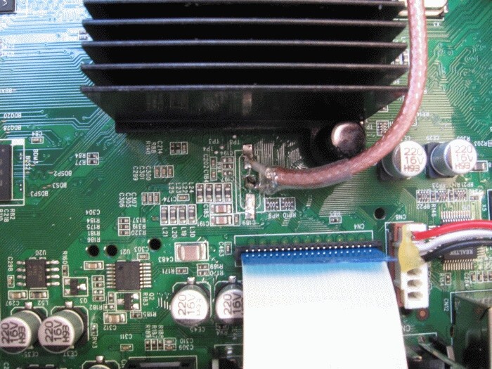 |
| Running the lead from the centre of the player keeps it away from the analog board. |
| Designation | Description | Replaced with |
| X1 | 27Mhz crystal | Remove |
| C194, C197 | Probably 33pf | Remove |
| Additional component | KTXO1 | 27Mhz Dexa D-Clock |
| Clock power supply |
Even though the Dexa D-Clock has the whole ground loop isolation thing going for it I still prefer to power it with a completely independent supply with it's own mains transformer. There's a convenient place to locate this in the front left (from the front) corner of the chassis which is also as far away from the analog sections of the player as possible.
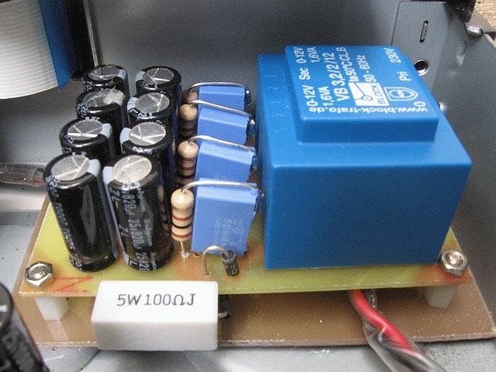 |
| A small Block transformer, some ultra fast diodes, the usual RC snubbers and an initial 6600 uf (8 x 820 Rubycon ZL) storage/filter caps. The supply leads then run under the drive to the other side of the chassis and via a low noise regulator to the clock. |
 |
| The clock supply is powered directly from the mains via a fuse and switched with a 5V/240V switching solid state relay activated by the main +5V rail on the power supply board. I've also replaced the IEC power socket with a better one which also includes an earth terminal which connects with the power supply low voltage side earth and hence to the chassis. Possible ground loop problems in the future will decide if this was a good idea or not. |
| Main power supply board |
A switch mode supply is what it is and other than replacing all of it with an analog supply about all you can do is upgrade the main diodes to ultra fast soft recovery types and improve the storage/filter caps on all the supply rails.
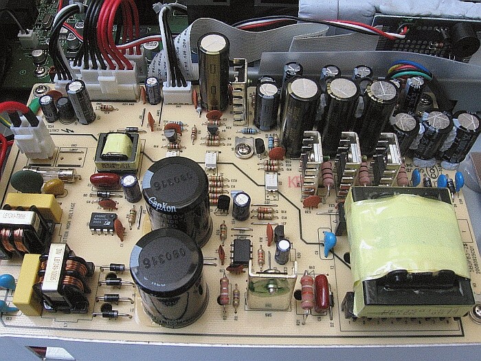 |
| Some of the new caps are just a tad big so they need to be offset a bit and then stabilized with some Blu-Tack. I didn't bother replacing the initial 68uf/450V CapXon filter caps because I'm not sure there's much to be gained by fitting only slightly better ones. |
| Designation | Description | Replaced with |
| D1, D3, D4, D5 | IN4007 | UF4007 |
| CE9, CE14, CE16, CE18 | 2200uf/16V Acon | 2200uf/25V Panasonic FM |
| CE10, CE17, CE19 | 1000uf/10V Acon | 1000uf/10V Rubycon ZL |
| CE11, CE15, CE20 | 1000uf/25V Mtdcon | 1000uf/25V Rubycon ZL |
| CE21 | 470uf/25V Acon | 470uf/35V Rubycon ZL |
| CE22 | 220uf/16V Acon | 220uf/25V Rubycon ZLG |
| CE12, CE13 | 470uf/25V Acon | 470uf/25V Rubycon ZL |
| CE7 | 470uf/10V Acon | 470uf/25V Rubycon ZL |
| Drive damping |
Now I have no idea if covering just about the entire top cover of the drive with Blu-Tack is actually improving the audio but it used to sound very "tinny" and resonant before. It's certainly very dead now (and not just when you tap on the Blu-Tack) and the Blu-Tack layer makes a nice connection with the now shielded and damped top cover of the player. I've also treated the plastic housing where I can and also the underside of the cup holder at the front of it as well as the underside of the fold down of the front of the chassis. There is less drive noise now and far less buzzing from other parts of the player as the laser seeks which on this player it does a lot.
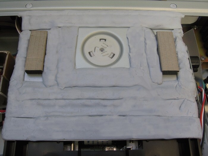 |
| Isn't Blu-Tack great, but here's an idea for Bostik. Coloured-Tack. Then we could get really creative. |
| Chassis damping and shielding |
The Oppo's chassis could at best be described as "flimsy" and from day one the folded top cover of my Oppo "buzzed" whenever a disk was playing and in the short term I solved this little problem with a small bag of lead shot. As copper shielding is very popular with makers of high end audio gear and as I shield everything else I mod or make I thought why not kill two birds etc. So I attached some single sided PCB offcuts to the top cover with some neutral cure silicone. Certainly damps the panel and when earthed via the copper braid earth strap no doubt shields as well which is probably a good thing as my passive pre sits on the next shelf up.
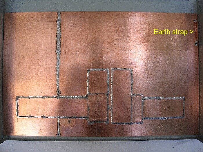 |
| The purpose of the additional 0.7mm thick copper plate strips will be explained shortly. The earthing strap mates with a similar one on the clock/power supply board sub assembly which is earthed to the chassis. |
The bottom of the player is also a bit flimsy even though it has several stamped dimple sections to help strengthen it. I filled these with yet more Blu-Tack as I also did for the four feet but the centre section underneath the drive was still a bit "tinny" so I stuck a piece of 15kg/m² lead sheet onto it with yet more neutral cure silicone. It's certainly dead now. The piece of lead weighs in at 900g and it and everything else that's been added have pushed the weight of the player up from it's intial 5.1kg to a now quality inspiring 7.7kg (17lbs).
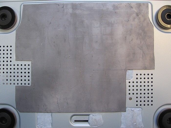 |
| Yeah it looks unsightly but when are you ever going to see it. |
| And that's about it, for now... |
But I do plan to change the DAC chip power supply caps and the +/- 12V supply caps (after the regulators and maybe replace them with Linear Technologies LT's) with Elna Silmic II's, perhaps also explore the transformer coupled output option and a few other things. Which only leaves the question of how good is this Oppo as a stereo CD and SACD player? The short answer to which is that once you improve a few, well quite a few parts of it, it's very good indeed, staggeringly good in fact. So why is this Oppo so good as a CD/SACD player? Well for a start it's a Blu-ray player and as way of further explanation (in a round about way) on this point...
A couple of years ago I attended a demonstration by a couple of guys who came all the way from Linn in Scotland of their Linn Klimax DS audio streaming technology. According to Linn, all CD/SACD players have a fundamental flaw in that they cannot in real time (as the disk is playing) read the contents of the disk accurately. So you get read errors and if the source or in this case the players interpretation of the source is flawed then it doesn't matter what you do afterwards because you're only trying to cover up the errors. They are serious about this and have since boldly announced the death of CD players and have stopped making them.
One reason perhaps that a CD/SACD player has trouble accurately reading a disk is because of limitations in the laser, the size of the beam compared to the pits and the servo tracking system that moves it. A CD only contains 700mb, a SACD 4.7gb (SACD total content only on one layer) and a Blu-ray disk contains on one layer 25gb. So a Blu-ray player has to be capable of reading much smaller pits packed much closer together so it uses a shorter wavelength laser (half that of a CD player). Not much of a leap to say that it will make easy and more accurate work of reading the bigger pits of a SACD and the much bigger pits of a CD.
Back to the Oppo and you do have to remember here that this is a US$499 machine and to be honest a rather cheaply built one at that. Don't get me wrong here, it's a great design and implementation of the various chips, some very nice firmware, well put together but just using the cheapest parts and construction methods possible. The fact that several companies in the USA who specialise in "modding" players for superior 2CH audio performance are offering "mod packages" for this player costing up to US$3000 speaks volumes about what this machine is capable of. That and a few other companies who are taking the guts of the Oppo, keeping most of it (or all of it in the case of Lexicon), putting a better chassis around it and their badge, and then selling them for many many times what the Oppo costs.
You might have gathered by now that I'm as impressed by this beast as others seem to be. There is a massive improvement in audio quailty over the stock machine and I now find it hard to find fault with it so for CD/SACD playback it has replaced my Marantz. It also plays DVD-Audio disks which is a bonus, not that I have many of them. I may have to buy another one though for Blu-Ray/DVD usage, either that or put up with future drive replacements as I wear them out as this will be getting a lot of use.