Vinyl might be making a comeback but finding preamplifiers or integrated amplifiers with a decent built in phono preamp isn't getting any easier.
In case you're wondering what a phono preamp is, it's an amplifier that takes the teeny weeny signal that comes out of a Moving Magnet cartridge or the output of a step up transformer if you're using an even lower output Moving Coil cartridge and amplifiers it enough so a normal preamplifier can use it.
It also needs to add RIAA equalization which applies +20db of boost at 20hz and -20db of cut at 20khz and a flat response at 1khz which is the inverse of the processing that takes place when pressing a record.
Additional attributes for a phono pre to have include very low noise, especially hum, as in the complete absence of it.
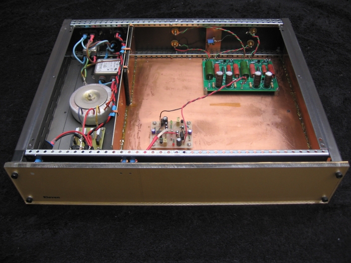
Yeah okay I'll admit that it's a bloody big box to house so few components especially when you can buy or build phono-pre's that will fit in the palm of your hand.
There are advantages to using a 19" steel rack mount enclosure as the basis of whatever you're building though, like not having to cram things together and it will at least match all the other 430mm wide commercial equipment you own.
The chassis is internally copper lined with single sided PCB stuck down with copious amounts of silicone which is also an effective dampening medium.
There is also some soft iron shielding between the transformer and circuit areas in the form of 4mm thick steel plate.
It's not a very big piece of steel but it does probably contribute in some small way to the 7kg overall weight.
|
Looks just like my main preamplifier with clear perspex over laser printed gold metallic paper, a subdued and rather lovely shade of pink pilot light and the same front panel branding of "Eleven".
For clues on where this comes from please refer to the film "This is Spinal Tap".
|
The power supply might be considered a bit of overkill as it only needs to supply a few tens of milliamps but when it comes to amplifiers, power supplies are very important as it's what you're really listening to.
As such it needs to deliver constant DC voltages, have low noise and most importantly of all have a very low output impedance.
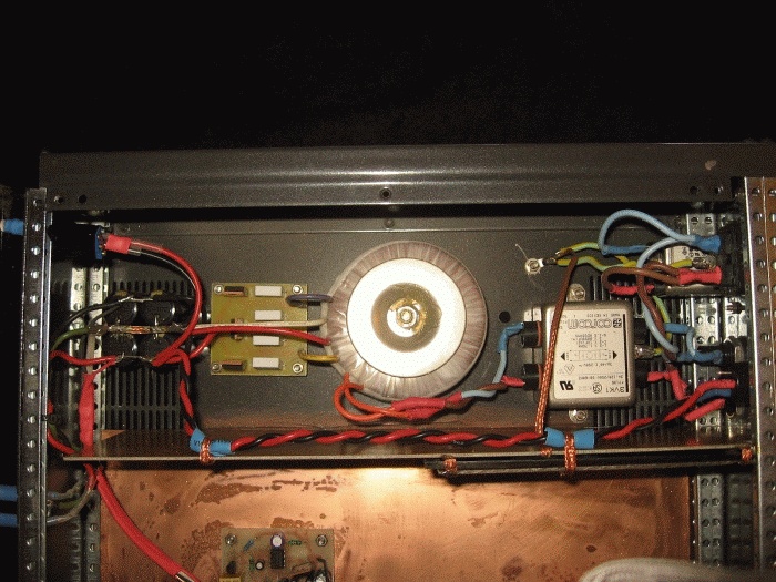
After the usual IEC socket/mains filter there's fuses on both active and neutral as there's no on/off switch, followed by an an additional filter, a 20 watt toroidal
transformer, Philips BYQ28E ultra fast recifiers, each bypassed with 10n MKP capacitors and 100 ohm resistors, feeding Panasonic FC main reservoir caps and all housed in it's own shielded enclosure.
 |
|
As well as providing power for the preamplifier there's an additional IEC 240V output socket to power the turntable as well as an 18V DC supply to power LED lighting for the turntable when the glass lid is raised.
|
This is followed by a Sulzer precision regulator delivering +/-15V.
Well it was but as an interim way of getting the new Boozhound Labs board going it's now delivering +/- 12.8V for the required 25.6V supply rail.
Not an ideal way of doing it but it will get replaced with a proper single voltage dedicated supply when I get around to it.
Which has now been done!
25.8V from a properly implemented ubiquitous LM317T.
A 10ohm non inductive resistor shunted with a 10n capacitor connects chassis earth to signal earth.
All the power supply wiring is pure silver (as is in fact all the wiring) 0.7mm round and 3.0mm x 0.15mm flat.
| Gain stages and RIAA equalization |
Having removed just about all the op-amps from my system I thought I might as well finish the job and get rid of the last ones which strangely enough were in my phono pre-amp.
A basic and very old National Semiconductor circuit using a LM4562 and a couple of OPA627's as output buffers which worked surprisingly well.
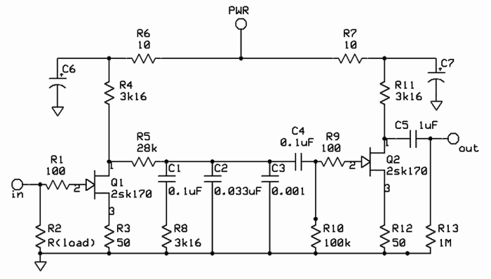
I have replaced this with something much simpler, a JFET two gain stages, passive EQ design from Boozhound Labs which to quote them is a...
"Minimalist audiophile phono stage using 2sk170 JFETs. Coupling and EQ caps are all Russian paper in oil.
High performance. Low budget. Available as a kit including the PCB and all the parts to complete it."
 |
|
You can't get much simpler than this.
Two single stage JFET gain stages with a passive RIAA equalization stage between them and no negative feedback.
C5 the 1uf output coupling capacitor has since been removed as it isn't required which leaves only the 0.1uf C4 in the signal path.
|
And indeed it is, put together in an hour or so and it works rather well.
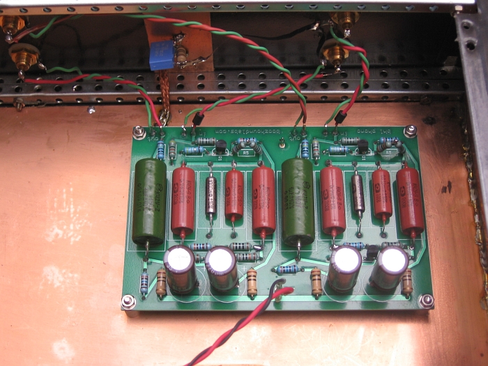
I've made a few minor changes though, including changing the Nichicon Muse supply rail caps to Elna Simlic II's and most of the resistors to Takman.
I've also increased the gain of the 2nd stage by reducing the value of R12 to 27ohms and I'm running it from 25.8 Volts.
The specs for the board say anywhere between 12V and 24V but the talk on the street is that it runs better on 24V than anything else and evidently if you increase the gain you need a little bit more voltage.
 |
|
Nice simple layout with plenty of room for the Russian K40-Y caps.
|
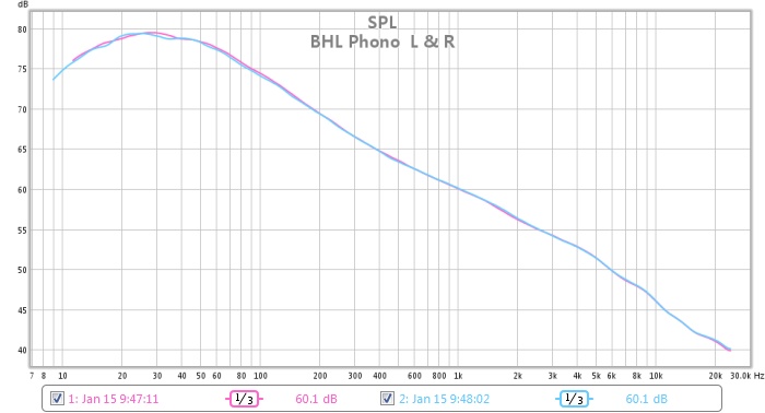
After a quick check on the CRO to make sure it was working and after having listened to it for some time I thought I'd better take some measurements.
Just to make sure it was hitting the right marks in terms of RIAA equalization and such things.
It's pretty close in fact, including the required rolloff at the bottom end although not as drastic as the 1976 IEC revision (7950us time constant) which resulted in a -3db rolloff at 20hz.
It's also perhaps a tad flat either side of 1khz so 0.8db high at 500hz and 1.3db low at 2122hz and also short at 20khz by 1db.
But does any of this really matter, well no because it sounds great and a really accurate frequency response is always low on the list of things you need to worry about anyway.
 |
|
Pretty close to the RIAA curve.
|
