| Home Turntable Phono CD Pre Speaker Multi Pre HT |
| Pre |
This section needs a complete update.
A buffer is a unity gain (usually) line stage with high input impedance, low output impedance and with decent output current ability so it will drive a load.
A good buffer will have low distortion, flat frequency response and high S/N (signal to noise) ratio as in not much of it (noise that is, not the ratio which should be high).
Solid state op-amps (operational amplifiers) are just made for this sort of thing so why would anyone use a valve (vacuum tube, electron tube, thermionic valve) for this role.
The answer of course is that you can achieve the requirements of a good buffer with valves and at the same time perhaps add some valve "magic", a bit of warmth rich in even order harmonics to the overall sound.
Well that's the theory at least but lets see how it all turns out.
You may well have noted elsewhere on this site that my current source selection/bass management/line stage uses op-amps with very low distortion and noise figures and I use very low distortion Class A amplifiers to drive my tweeters.
So why would I want to add something with perhaps 1000 times more distortion and 20-30db more noise.
Good question. Perhaps I'm getting old and stupid, or maybe just longing for earlier times when things were simpler.
Anyway here's a photo of the finished product so as to encourage you to read on.
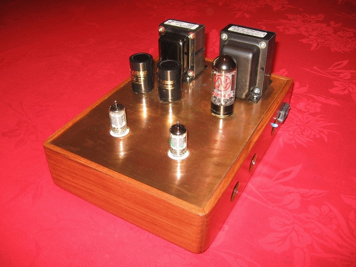
Just like a bought one? Well maybe not like anything you've bought recently but I like the look of it and I think that the timber and copper work well together. Not visible in this photo are the nice feet in matching (to the electrical parts) chrome and black.
| Chassis |
You can build a valve buffer, or valve preamplifier or even a valve power amplifier for that matter and make it look just like any other piece of modern audio equipment. A box with all the bits hidden inside but for me part of the valve magic is seeing all the parts, the transformers, chokes and most importantly the valves themselves. So it's old school for me with a wooden plinthe and top plate with all the major components arranged on it.
Now I'll be the first to admit that my wood working skills especially when it comes to mitre joints and such aren't top notch but a few hours work over as many days turned a length of no doubt endangered rainforest timber with a rather attractive colour and grain into a fairly good approximation of a wooden plinthe.
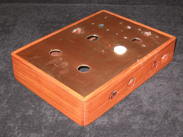
The wooden plinthe and copper top plate shown here in unfinished form. The timber used was 19mm x 68mm Northern Box which is a common decking timber, very hard and long wearing which is important when you get a lot of foot traffic.
Inside the plinthe there's another chassis made from single sided printed circuit board. This provides shielding and a suitable platform onto which mount the various components. The copper top plate sits on top of this, fixed with silicone and recessed into a 10mm wide, 4mm deep routed rebate cut into the plinthe. Timber and copper top then had several coats of Cabot's Gloss CFP (Clear Flooring Polyurethane) applied for a nice gloss finish.
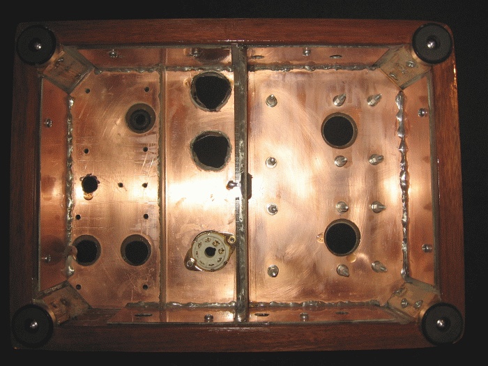
The advantage of a second internal chassis is that you can mount sockets, standoffs for boards and anything else and then hide all of the fixings for these with the top plate.
| Power supply |
The heart of any good amplifier is it's power supply and as I'm doing this project in the "old fashioned way" then there's nothing to it but to use an unregulated, valve rectified, choke filtered supply complete with chassis mounted can electrolytics.
The transformer is a Hammond 370CAX delivering 250-0-250 Volts at 70ma as well as 5 and 6.3 Volt filament windings and the 20H choke is also by Hammond, a 193C model rated at 100ma. Full wave rectifier is a JJ GZ34 which allows a nice slow turn on for the B+ rail and the filter capacitors are Mundorf M-Lytic HV's and Evox-Rifa. The 120 ohm 5W resistors in series with the 250V secondary windings aren't really needed as there's enough resistance in the transformers windings to supply the rectifiers required limiting resistance but as I had more voltage than I needed I saw no harm in including them.
Main B+ rail after the choke is 320V before being split and dropped to 260V for each channel. Heaters run from 6.15V rather than the usual 6.3V so as to reduce noise and extend tube life slightly. Total current draw for both channels at idle as well as the B+ rail LED indicator and 4ma bleed is 30ma which is more than enough for the 20H choke to work as a filter.

A more or less typical power supply layout with B+ taken from the centre tap of the 5V filament winding and both windings bypassed to earth to help reduce noise.
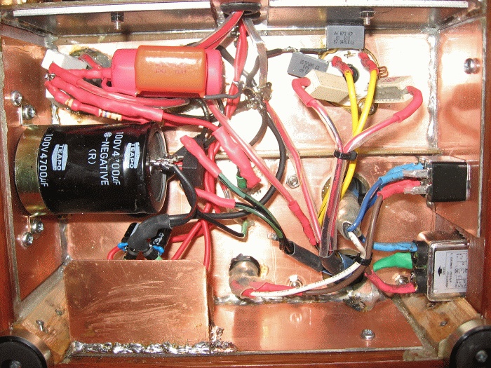
This is a bit more of a rats nest than I would have hoped for but that's point to point wiring and star earthing! Additional shielding in the form of 3mm thick mild steel plate can be seen top of picture affixed and earthed to the copper separator plate that divides this section from the amplifier one. The regulated heater supplies (bottom left under the copper heatsink) have since gone, replaced with series dropping resistors (KISS).
| The buffer |
The circuit is a standard common cathode Class A amplifier, two of them cascaded with some negative feedback (NFB) applied to tame distortion, improve bandwidth and get the output impedance down. It's based on a standard textbook design from a local magazine (Silicone Chip) which used a 12AX7 but I'm using 12AU7's instead because they make a much better line driver. And why not more linear 6DJ8's or 6SN7's, well because I'd rather use the much maligned 12AU7 and in this layout they work nicely.
For intial construction and testing I used a couple of 12AU7's that Mark Houston (the guy who got me heading down this path) was kind enough to give me and then I tried some NOS (New Old Stock) JAN (Joint Army Navy) Philips 5814A's but I've since acquired some nice 60's NOS RCA "Clear Top" 12AU7A's. I chose these because I lean more towards clean, detailed and good resolution rather than warm, smooth and creamy rich but I'll no doubt get around to trying British Mullard, Dutch Amperex or Philips and German Telefunken tubes in future.
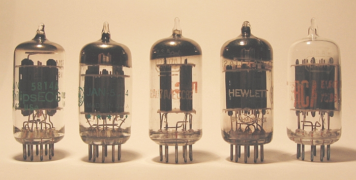
A selection of valves, Philips 5814A, GE Triple Plate 5814A, RCA 12AU7A, Amperex 12AU7A and RCA 12AU7A Cleartop. All NOS except for the Amperex which came out of some Hewlett Packard test gear.
It would appear that 12AU7's like to run with about 5ma of plate current at idle and around 150V plate voltage as that's what everybody else seems to be using. I did try much higher plate currents but eventually settled on a tad over 5ma so it would appear that everybody else is correct. For the second half of the triode (the line driver) this amounts to 135V on the plate and -4V on the cathode.
The first stage is a little trickier as the cathode resistor forms part of the NFB loop so you need to keep the cathode resistor value as high as possible, in this case 1.1k to keep the feedback ratio low (so there's more of it, go figure) and to prevent excessive loading of the second triode. This results in a cathode voltage of -5.7V and a plate voltage of 160V, a tad higher than required but within reason.
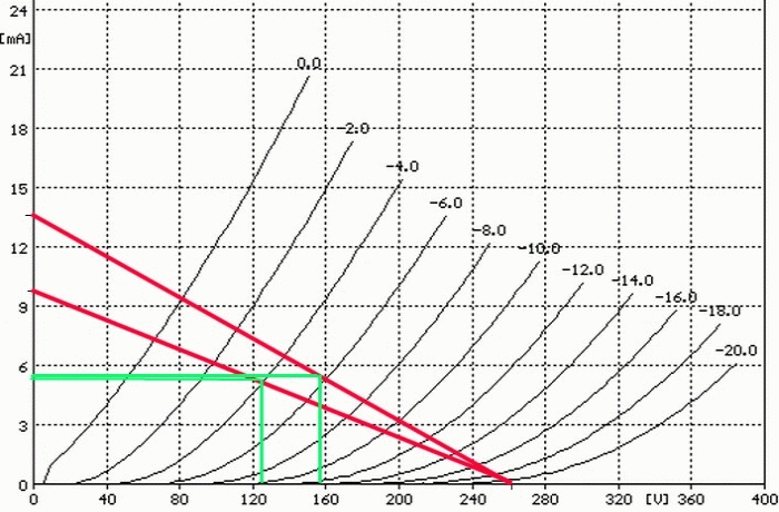
This is what the Plate voltages and currents should be.
Total feedback ratio is the sum of the feedback resistor (10k) and the cathode resistor (1.1k) divided by the cathode resistor, ie. (10k + 1.1k) / 1.1k = 10:1 and overall voltage gain is 7. Which is way more than you need in a "unity gain" buffer so I'll be using a voltage divider in the following active crossover stage to trim it back down to unity. This arrangement maintains the low output impedance of the buffer so it will drive the cable and input op-amp without loss and also has the advantage of increasing the effective signal to noise ratio of the buffer by a factor of 7.

It's hard not to love valves when you see how few bits you need to make them work.
I've used the printed circuit boards from the original SC design, shortened and with unwanted tracks removed but in hindsight it would have been just as easy to mount the valve socket on standoffs and use point to point wiring. Nothing special parts wise, metal film resistors in and bypassing the signal path, carbon everywhere else and Mundorf MCap Supreme capacitors.
I've tried to keep it neat and simple with a logical layout to minimise signal path length and to keep everything that needs to be kept away from anything else kept away, so to speak. As such the input and output RCA sockets are mounted to each side rather than the more conventional rear of the unit as this results in far less noise and especially hum pickup.
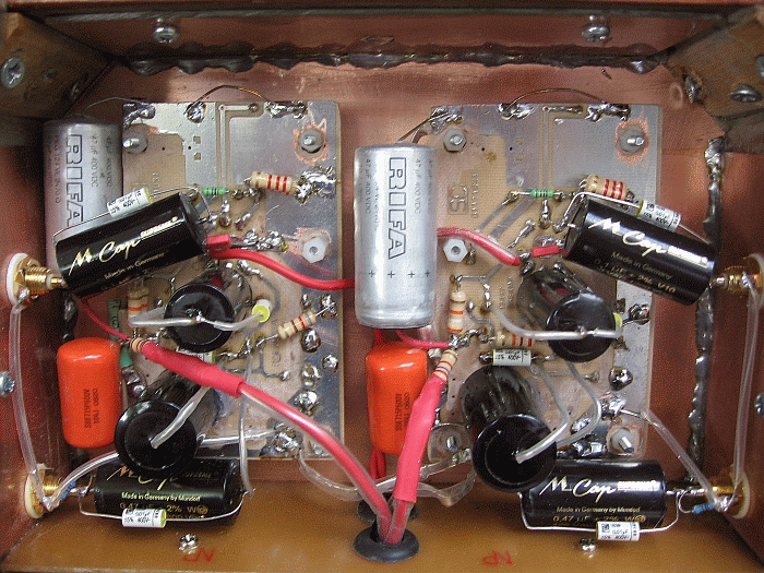
The problem with valve construction is the size of the high voltage capacitors but I've tried to make use of this at least for connection to the input/output sockets. Other than that it's fit them in where you can. As the metal case of the Rifa's is negative they've been sleeved with clear heatshrink to stop any shorts to ground and resulting unwanted earth loops. Additional 10nf Vishay 1839 MKP's bypass all the Mundorf coupling caps.
| So how does it sound? |
My audio system is very much slanted towards accurate rather than musical. I like to hear what's in the source, all of it, rather than just a representation of it that I find pleasing. The later option seems popular amoungst some audiophiles who are often "tuning" some part of their system, by component choice or adding more components to the signal path than are needed in order to achieve the desired sound.
I'd rather stick with properly implemented sound engineering rather than snake oil but here I am adding a "buffer" to the signal path that quite franky isn't really needed. A tube buffer at that, with comparitively much more noise and distortion than any of the components preceeding it. And it's not that I'm trying to tame digital hashness because even with digital sources it's often been commented that my system has a very analog sound. A very revealing analog sound, which isn't surprising given the way the system and the room is setup, but not cold, harsh or clinical like digital can be.
So looking at the negative aspects of adding a tube buffer to the signal path which would be principly, noise and distortion. I don't like noise at all, be it hiss, hum, buzz, clicks or pops and there is none of it in my system. Okay, there's a very very slight amount of hiss if you stick your ear right up against the tweeters with the system running flat out (0db attentuation) but that's it.
This buffer adds very little additional hiss and what there is a nice soft sort of hiss, which considering it's after the main system attenuator and therefore in the worst place for S/N is pretty good. There is no additional hum or buzz at all. None. And that's a result of good filtering, a very good power supply and supply rail decoupling, proper layout including noisy and quiet earth as per current solid state circuit practices. As a result it's also completely immune from any mains borne clicks, pops, hash or switching tones and RF for that matter.
So that leaves distortion which strictly speaking you would treat as a negative but as we all know there's distortion and then there's distortion. Tubes, whilst having lots of distortion are rich in even harmonics which sound nicer than odd harmonics. 12AU7's, whilst considered to be more non linear and therefore causing more distortion than most comparable tubes have a distortion spectrum that is richer in 2nd harmonics. And this design does use NFB, not as much as it could but still enough to bring the distortion down to reasonable levels.
So how does it sound, well it's still early days but my initial thoughts are that I like it. I've lost very little if anything in the way of detail, top end or bottom end. The soundstage and depth have, if anything improved and there's a fullness to the sound, especially the upper bass and midrange that simply wasn't there before. Gee, maybe I have openend that bottle of snake oil.
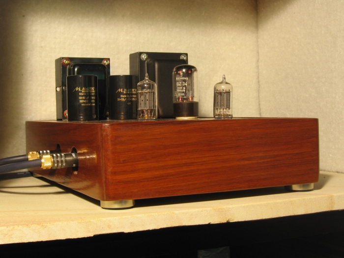
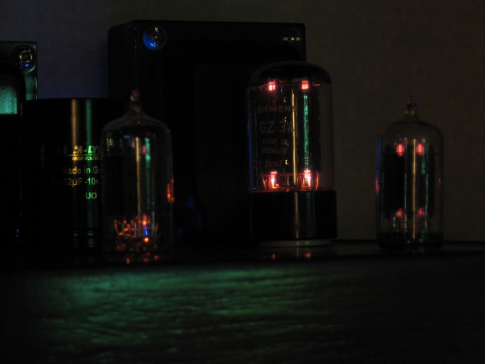
You can say a lot of things about tubes but one thing you can't deny is how nice they are to look at.